
Gas Spring Calculator
PRO EDITION • Physics-Based • Mobile + Desktop
Gas springs are essential components in various applications like gas spring calculator, from automotive tailgates to industrial machinery and furniture. Calculating the correct force required for your gas springs is crucial for optimal performance and safety. Our Gas Spring Force Calculator simplifies this process, providing accurate results based on your specific parameters. This guide will walk you through using the calculator effectively.
Understanding the Formula
The calculator uses the following formula to determine the required gas spring force Calculator:
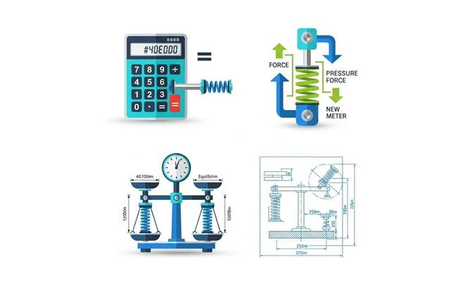
F₁ = ((m × RH) / (2 × N × x₂) + 5) × 9.81
Where:
- F₁ = Gas spring force in Newtons (N)
- m = Weight of the object in kilograms (kg)
- RH = Length of the tailgate/object in meters (m)
- N = Number of gas springs
- x₂ = Distance from rotation axis to gas spring mounting point in meters (m)
This formula accounts for the mechanical advantage, number of springs, and adds a constant safety factor before converting to Newtons.
Step-by-Step Guide to Using the Gas Spring Calculator
Step 1: Access the Calculator
Navigate to the Gas Spring Force Calculator on our website. You’ll find a clean, intuitive interface with clearly labeled input fields.
Step 2: Enter the Weight (m)
- Locate the “Weight of object (m)” field
- Enter the total weight of the object to be lifted or supported
- Use kilograms as the unit (e.g., 25 kg for a typical tailgate)
- This value must be greater than zero
Step 3: Input the Length (RH)
- Find the “Length of tailgate (RH)” field
- Enter the length of the tailgate or object being lifted
- Use meters as the unit (e.g., 1.2 m for a standard tailgate)
- This can be measured from hinge point to farthest point
Step 4: Specify the Distance (x₂)
- Locate the “Distance from rotation axis (x₂)” field
- Enter the distance between the rotation axis and where the gas spring will be mounted
- Use meters as the unit (e.g., 0.3 m)
- This value affects the mechanical advantage of the spring
Step 5: Set the Number of Gas Springs (N)
- Find the “Number of gas springs (N)” field
- Enter how many gas springs will be used in your application
- The default is 2, which is common for many applications
- Using more springs distributes the force requirement
Step 6: Calculate the Force
- Click the “Calculate Force” button
- The calculator will process your inputs using the formula
- Results will appear immediately in the results section
Step 7: Review the Results
The results section displays:
- Your input values for verification
- The calculated force in Newtons (N)
- A visual diagram showing the relationship between parameters
Parameter Explanation
Weight (m)
This is the total weight of the object that the gas spring(s) need to lift or support. It’s crucial to include all components that will be moved, not just the main structure.
Length (RH)
The length of the tailgate or object being lifted, measured from the rotation axis (hinge point) to the farthest point. This affects the torque that needs to be counteracted.
Distance (x₂)
The distance between the rotation axis and the point where the gas spring is mounted. A smaller distance requires more force, while a larger distance provides more mechanical advantage.
Number of Gas Springs (N)
How many gas springs will be used in your application. Using multiple springs distributes the force requirement and provides redundancy.
Example Calculation
Let’s walk through a practical example:
Suppose you have:
- Weight (m): 30 kg
- Length (RH): 1.5 m
- Distance (x₂): 0.4 m
- Number of springs (N): 2
Using the formula:
F₁ = ((30 × 1.5) / (2 × 2 × 0.4) + 5) × 9.81
F₁ = ((45) / (1.6) + 5) × 9.81
F₁ = (28.125 + 5) × 9.81
F₁ = 33.125 × 9.81
F₁ ≈ 325 N
Thus, you would need gas springs with approximately 325 Newtons of force each.
Tips for Accurate Calculations
- Measure precisely: Use accurate measurements for all parameters
- Consider safety factors: The formula includes a +5 constant, but you might need additional safety margin for your specific application
- Account for all weight: Include all components that contribute to the total weight
- Environmental factors: Consider temperature variations that might affect gas spring performance
- Consult professionals: For critical applications, always verify calculations with an engineer
Common Applications
Gas springs are used in various industries:
- Automotive: Tailgates, hoods, hatchbacks
- Furniture: Adjustable chairs, lifting mechanisms
- Industrial: Machinery guards, access panels
- Medical: Adjustable beds, equipment positioning
- Aerospace: Access panels, cargo doors
Troubleshooting
If you’re getting unexpected results:
- Verify all units are correct (kg for weight, m for distances)
- Ensure all values are positive numbers
- Check that the distance x₂ is significantly less than RH
- Confirm the number of springs is appropriate for your application
FAQ/Frequently Asked Questions
Our Gas Spring Force Calculator provides a quick and accurate way to determine the appropriate gas spring force for your application. By following this step-by-step guide and understanding the formula behind the calculations, you can ensure optimal performance and safety in your projects.
Remember that while this calculator provides a reliable estimate, critical applications should always be verified by a qualified engineer. Proper gas spring selection is essential for both functionality and safety. Bookmark the calculator for future use, and feel free to experiment with different values to understand how each parameter affects the required force.
You can explore Similar Calculator like this Towing Estimate Calculator 2025